H1 Product Description

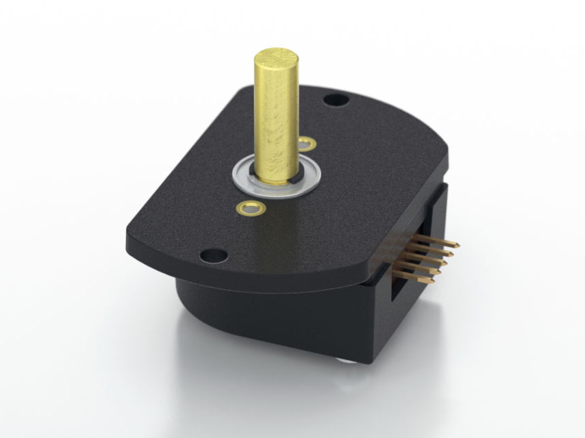
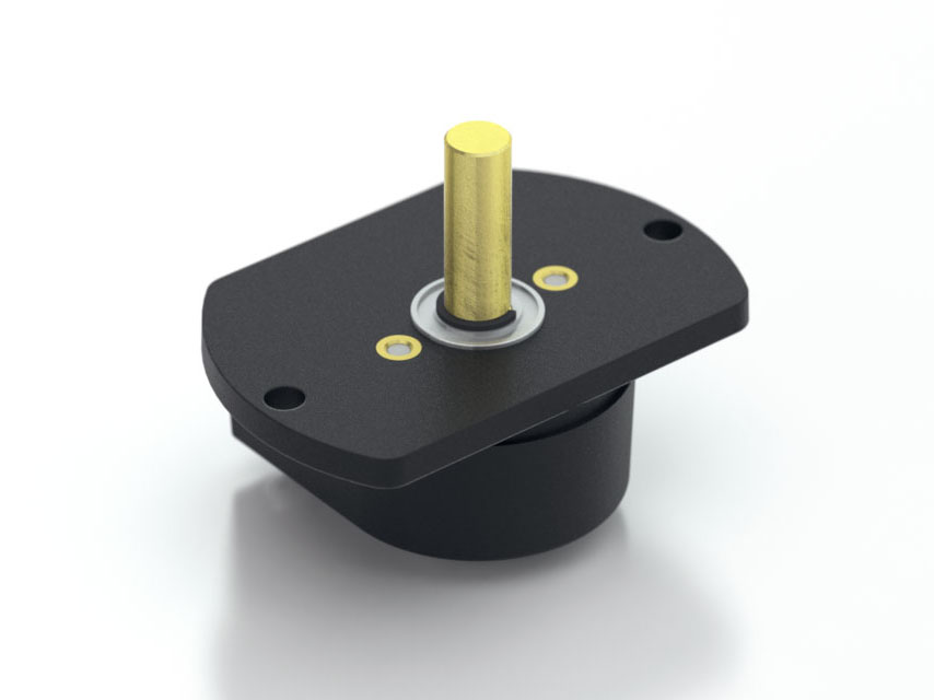
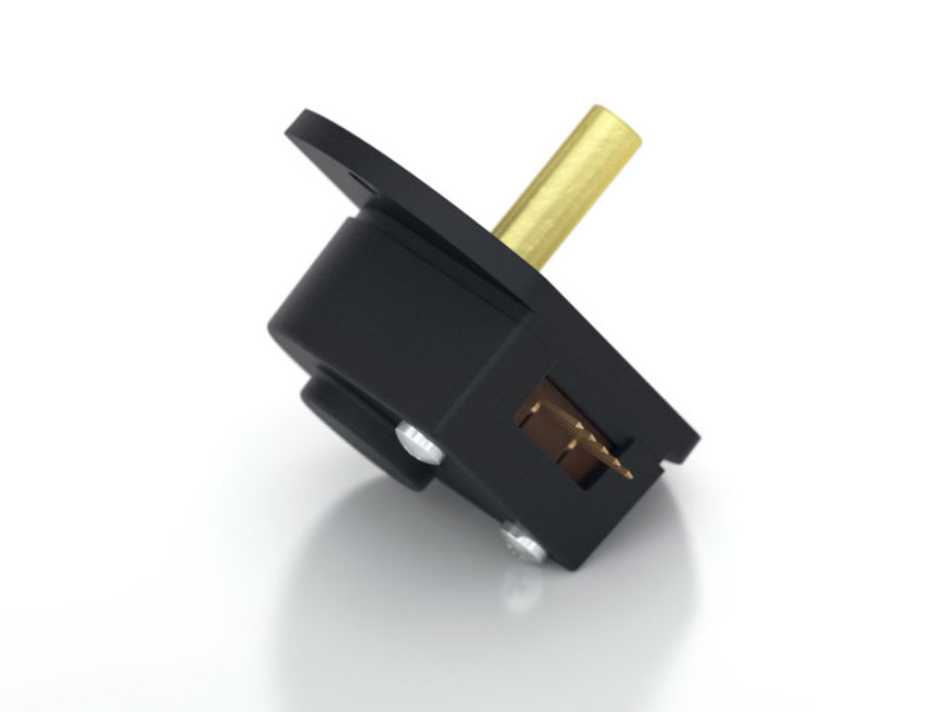
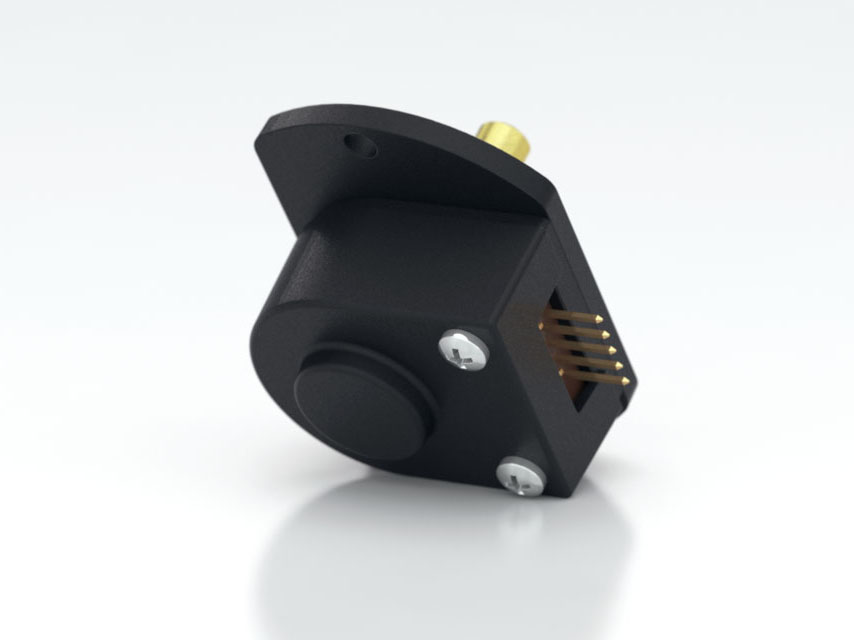
The H1 series ball-bearing optical shaft encoder has a glass-filled polymer enclosure. This non-contacting rotary to digital converter is designed to provide digital feedback information. The H1 is fully assembled with a brass shaft, two 1/4 in. ID by 1/2 in. OD ball bearings, and a mounting plate. The mounting plate comes with 2 mounting holes for #4 size screws.
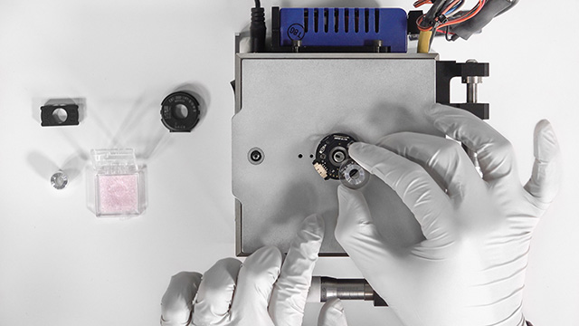
The H1 is designed to drive cables up to 10 feet long. For longer cable lengths, adding a PC4/PC5 differential line driver is recommended. A connection to the H1 series encoder is made through a 5-pin standard connector. The mating connectors are available from US Digital with several cable options and lengths.
Product Specifications
View here or download the specifications
ENVIRONMENTAL
| PARAMETER |
VALUE |
UNITS |
| Operating Temperature, CPR < 2000 |
-40 to 100 |
C |
| Operating Temperature, CPR ≥ 2000 |
-25 to 100 |
C |
| Electrostatic Discharge, IEC 61000-4-2 |
± 4 |
kV |
| Vibration (10Hz to 2kHz, sinusoidal) |
20 |
G |
| Shock (6 milliseconds, half-sine) |
75 |
G |
MECHANICAL
| PARAMETER |
VALUE |
| Max. Acceleration |
100000 rad/sec² |
| Max. Shaft Speed (mechanical) |
10000 RPM (1) |
| Max. Shaft Torque |
0.05 in-oz |
| Max. Shaft Loading |
2 lbs. |
| Bearing Life |
life in millions of revs = (90/P)³
where P = radial load in pounds |
| Weight |
1.49 oz. |
| Max. Shaft Runout |
0.006 in. T.I.R. |
| Mounting Plate Screw Torque |
(#4-40) 4-6 |
| Moment of Inertia |
0.001 oz-in-s² |
| Technical Bulletin TB1001 - Shaft and Bore Tolerances |
Download |
(1) The maximum speed due to electrical considerations is dependent on the CPR. See the EM1 and EM2 product pages.
PHASE RELATIONSHIP
B leads A for clockwise shaft rotation, and A leads B for counterclockwise rotation when viewed from the shaft side of the encoder.
ELECTRICAL
- Specifications apply over the entire operating temperature range.
- Typical values are specified at Vcc = 5.0Vdc and 25°C.
- For complete details, see the EM1 or EM2 product pages.
| PARAMETER |
MIN. |
TYP. |
MAX. |
UNITS |
CONDITIONS |
| Supply Voltage |
4.5 |
5.0 |
5.5 |
V |
|
| Supply Current |
|
27 |
33 |
mA |
CPR < 500, no load |
| |
54 |
62 |
mA |
CPR ≥ 500 and < 2000, no load |
| |
72 |
85 |
mA |
CPR ≥ 2000, no load |
| Low-level Output |
|
|
0.5 |
V |
IOL = 8mA max., CPR < 2000 |
| |
|
0.5 |
V |
IOL = 5mA max., CPR ≥ 2000 |
| |
0.25 |
|
V |
no load, CPR ≥ 2000 |
| High-level Output |
2.0 |
|
|
V |
IOH = -8mA max. and CPR < 2000 |
| 2.0 |
|
|
V |
IOH = -5mA max. and CPR ≥ 2000 |
| |
4.8 |
|
V |
no load and CPR < 2000 |
| |
3.5 |
|
V |
no load and CPR ≥ 2000 |
| Output Current Per Channel |
-8 |
|
8 |
mA |
CPR < 2000 |
| -5 |
|
5 |
mA |
CPR ≥ 2000 |
| Output Rise Time |
|
110 |
|
nS |
CPR < 2000 |
| |
50 |
|
nS |
CPR ≥ 2000, ± 5mA load |
| Output Fall Time |
|
100 |
|
nS |
CPR < 2000 |
| |
50 |
|
nS |
CPR ≥ 2000, ± 5mA load |
PIN-OUT
| PIN |
DESCRIPTION |
| 1 |
Ground |
| 2 |
Index |
| 3 |
A channel |
| 4 |
+5VDC power |
| 5 |
B channel |
PRODUCT CHANGE NOTIFICATIONS
| Title |
Date |
Description |
Download |
| E2 & H1 Material Change - 7191 |
8/22/2022 |
As part of our ongoing continuous improvement program, as well as considering the current state of the plastics industry supply chain disruptions, US Digital has decided to focus on the standardization of our plastic encoder components. Based on this, the E2 and the H1 encoder covers and bases will be changing from PBT 20% GF
(polybutylene terephthalate) to PC 20% GF (polycarbonate). This change has no impact on the form, fit and function of these encoders. |
Download |
| H1 Mold Update - PCN 5259 |
4/21/2015 |
As part of our ongoing continuous improvement efforts, and in order to enhance both function and appearance of the H1 product line, multiple improvements are being incorporated into a plastic component redesign. |
Download |
| EM1 & EM2 Update - PCN 4199 |
1/14/2014 |
Based on our continuous process improvement program, US Digital is changing the current marking method for our EM1 and EM2 encoder modules to a serialization method. This change will allow for each module to have a unique code; the current marking method is based on a date code system that includes all encoder modules produced within a specific week / year. The serialization system will be based on a hexadecimal system. |
Download |
| EOL Sealed Housing Option - PCN 1021 |
4/11/2013 |
This PCN is a formal notification that US Digital is discontinuing the Sealed Housing option for the following products:
- A2 Absolute Optical Encoder
- A2T Absolute Optical Inclinometer
- H1 Ball Bearing Optical Shaft Encoder
- H3 Ball Bearing Optical Shaft Encoder
- S1 Optical Shaft Encoder
- S2 Optical Kit Encoder
The Sealed Housing option provides the encoder with low level capability of surviving in moisture environments, however the encoder is NOT water proof or intended to be used in applications where this is required. |
Download |
| EM1 LED Die - PCN 1016 |
2/7/2013 |
As part of US Digital's continual assurance of supply strategy, we have qualified additional sources for our LED die used in our EM1 encoder module, which in turn impacts all of the following products:
EM1, E2, E3, E5, E6, H1, H15, H3, H5, H6, HB5M, HB6M, HD25, PE, S1, S2, S5, S6, T5 and T6
The device specification will remain the same, i.e. there will be no change to form, fit or function of the product(s) as specified by US Digital. The appropriate quality and reliability testing has been performed on representative products to ensure normal parametric distribution, consistent with US Digital's quality and reliability standards. |
Download |
Additional Information
Product Notes
-
Cables and connectors are not included and must be ordered separately.
-
US Digital® warrants its products against defects in materials and workmanship for two years. See complete warranty for details.
Datasheets
Related
3D Model Downloads
Please
configure your product first
to download a 3D model.
(Note: The formats below will become links if there are 3D models available.)
-
SolidWorks Format
-
IGES Format
-
Parasolid Format
-
STEP Format
Product Configurator
Our products are not currently available for direct online purchase. To place an order please contact us directly with your part number.
For purchasing or volume discounts, please configure the part above, then use the completed part number and contact us!
Feedback
US Digital's mission is a commitment to quality and constant improvement. If you find an error to a product on this page, please let us know!